Meshes and domains
Like many finite element codes, magnum.fe solves problems on arbitrary tetrahedral meshes. Depending on the complexity of the geometry, the creation of suitable meshes can be quite challenging. magnum.fe comes with built-in meshing capabilities for simple geometries. For complex geometries it is recommended to use specialized external meshing tools. Meshes generated this way can be converted to magnum.fe compatible files with the conversion tool magnum.msh.
Built-in meshing tools
Since magnum.fe is built on top of the finite-element library FEniCS the meshing capabilities of FEniCS are also available in magnum.fe. Regular box shaped mesh can be generated in the simulation file by
BoxMesh(Point(0,0,0), Point(1,1,1), 10, 10, 10)
More complex geometries can be generated with the library mshr that is part of the FEniCS distribution that comes with magnum.fe. With mshr the geometry can be defined by combining simple geometric shapes, e.g.
from magnumfe import *
import mshr

# Define 3D geometry
sphere = mshr.Sphere(dolfin.Point(0, 0, 0), 0.5)
cone   = mshr.Cylinder(dolfin.Point(0, 0, 0), Point(0, 0, -1), .35, .1)
sample = cone + sphere

# Create mesh
mesh = generate_mesh(sample, 16, "cgal")
More examples can be found in the demo directory of mshr.
Marking domains in meshes
Micromagnetic problems often involve different materials. For instance a magnetic sample might be composed of layers with different magnetic material parameters. That means that magnum.fe has to be aware of different regions within the mesh. These regions can be either volumes (cell domains) or areas (facet domains).
FEniCS and hence also magnum.fe offers two possibilties to attach domain information to meshes. The first one is to store the information in the mesh as a MeshDomains object. The other possibilty is to keep the domain information apart from the mesh in so-called MeshFunction objects. For details please refer to the FEniCS manual that is available under http://fenicsproject.org/documentation/. However, if you use external meshing programs and convert the meshes the domain information is automatically generated and you will not have to deal with the details of MeshDomains and MeshFunction classes.
Converting meshes
If you use external programs for the mesh generation, there are two ways to convert the generated meshes in order to use them in your magnum.fe simulation. FEniCS comes with the conversion tool dolfin-convert that is able to convert a number of different formats to the required XML format. Type dolfin-convert -h in a terminal to get a help along with a list of supported formats. Note, that dolfin-convert stores domain information as MeshFunction in distinct files. Conversion of sample.msh to sample.xml can be done with
dolfin-convert sample.msh sample.xml
which creates the files sample.xml, sample_facet_region.xml, and sample_physical_region.xml. While sample.xml contains the mesh information, sample_facet_region.xml and sample_physical_region.xml contain the facet domain and the cell domain data respectively. In order to load the mesh information into a magnum.fe state, call
mesh = Mesh("sample.xml")
cell_regions  = MeshFunction("size_t", mesh, "sample_physical_region.xml")
facet_regions = MeshFunction("size_t", mesh, "sample_facet_region.xml")
state = State(mesh, cell_markers = cell_regions, facet_markers = facet_regions)
However, the recommended way to convert a mesh into magnum.fe XML format is to use the meshing tool magnum.msh that ships with magnum.fe. magnum.msh supports a variety of mesh formats and is able to create a single XML file that contains not only the mesh, but also the domain information. To convert sample.msh, type
magnum.msh sample.msh sample.xml
Since magnum.msh includes the domain information in the XML file, the state can simply be initialized with
state = State(mesh)
magnum.fe uses numerical IDs to address different domains. In the case of named domains, like for instance in MED files, magnum.msh will show the mapping of the named to the numered domains:
Read sample.med ... done

9 named domains found:
----------------------------------------
Type  | ID  | Name
------+---------------------------------
facet |   1 | contact-top
facet |   2 | contact-bottom
cell  |   1 | electrode-bottom
cell  |   2 | FePt
cell  |   3 | pinned
cell  |   4 | Cu
cell  |   5 | free
cell  |   6 | electrode-top

Write sample.xml ... done
Creating a shell for the shell transformation method
Besides format conversion, magnum.msh is also able to create a cuboid shell around a given mesh as required by the shell transformation method. In order to create a cuboid shell around a mesh you have to prescribe the discretization of the shell and the margin bewteen original mesh and shell
magnum.msh -s 3x4x4x4 -m 1.0 sphere.msh sphere.xml
This command reads a mesh from sample.msh and generates a shell with 3 layers and \(4 \times 4 \times 4\) cells that has a margin of 1.0 to the original mesh. The resulting mesh is shown in Fig. 5.
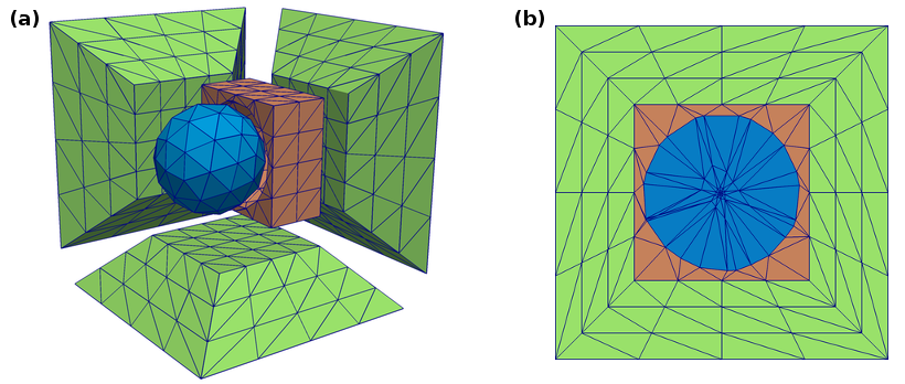
Fig. 5 Mesh of a sphere including cuboid shell for the solution of open-boundary problems. (a) Explosion view (b) Cross section
Creating a multilayer structure with Gmsh
A very powerful open source mesh generation tool is Gmsh. In this section the generation of a simple circular multilayer stack with Gmsh is described in detail. The geometry in Gmsh is usually defined dimension by dimension. That means that points are connected to lines, lines are connected to surfaces and surfaces are connected to volumes.
In order to create the geometry, create an empty ASCII file called stack.geo and open it in the editor of your choice. We start by defining a meshing constant cl that gives a measure for the edge length of the tetrahedra.
cl = 3.0;
Next we define a couple of points that we need to describe the circular base area of the stack.
Point(1) = {  0,  0, 0, cl};
Point(2) = { 10,  0, 0, cl};
Point(3) = {-30,  0, 0, cl};
Point(4) = { 30,  0, 0, cl};
Point(5) = {  0, 30, 0, cl};
Point(6) = {  0,-30, 0, cl};
Note that every point has a unique ID (Point(ID)) and besides the three spatial coordinates it is assigned the discretization constant cl. In the next step the points are used to define the segments of the circular base area.
Ellipse(1) = {5,1,2,3};
Ellipse(2) = {4,1,2,5};
Ellipse(3) = {6,1,2,3};
Ellipse(4) = {4,1,2,6};
The ellipse command requires four arguments, namely the start point of the arc, the center of the arc, an arbitrary point on the major axis of the ellipse, and the end point of the arc. The segments are now connect to a line loop and the line loop is used to define a surface.
Line Loop(5) = {1,-3,-4,2};
Plane Surface(1) = {5};
A simple possibilty to create a stack from a base area is extrusion, which is done with in Extrude command in Gmsh
s0[] = Extrude{0, 0, 5.0} {Surface{1}; Layers{2};};
As first argument the Extrude command expects a vector that gives direction and length of the extrusion. In the second argument the surface to be extruded is given. The additional Layers command tells Gmsh to extrude the surface mesh in a regular fashion using a defined number of cell layers. The surfaces and regions created by the extrusion are returned in a list and saved to the variable s0. Subsequent layers are generated by
s1[] = Extrude{0, 0, 10.0} {Surface{s0[0]}; Layers{2};};
s2[] = Extrude{0, 0,  1.5} {Surface{s1[0]}; Layers{1};};
s3[] = Extrude{0, 0,  3.0} {Surface{s2[0]}; Layers{5};};
s4[] = Extrude{0, 0,  5.0} {Surface{s3[0]}; Layers{2};};
Now that all volumes and surfaces are defined they have to be declared as physical volumes and surfaces in order to make them addressable in magnum.fe.
Physical Volume(1) = {s0[1]};
Physical Volume(2) = {s1[1]};
Physical Volume(3) = {s2[1]};
Physical Volume(4) = {s3[1]};
Physical Volume(5) = {s4[1]};

Physical Surface(1) = {1};
Physical Surface(2) = {s4[0]};
The numerical IDs defined by Physical Volume(ID) and Physical Surface(ID) are available in magnum.fe later on. Save the file and create the mesh from the geo file by calling gmsh -3 stack.geo on the command line. This should create a stack.msh file. Note, that Gmsh sometimes fails to create the mesh especially when it comes to regular extrusion. In this case repeated calls to Gmsh usually fix the problem. In order to use this mesh within magnum.fe you can convert it by calling magnum.msh stack.msh stack.xml. Fig. 6 shows the resulting mesh with its cell domains and facet domains.
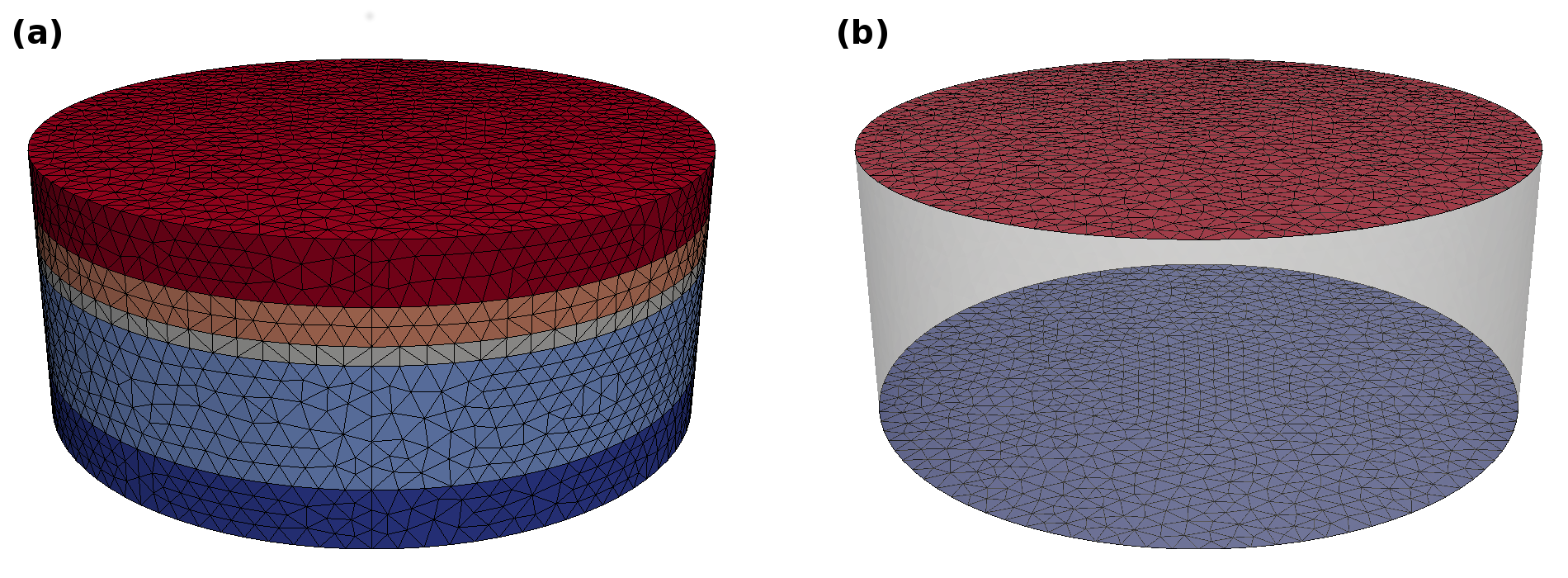
Fig. 6 Simple circular stack generated with Gmsh (a) Cell domains (b) Facet domains
For a complete reference to Gmsh please refer to the Gmsh manual that is available under http://geuz.org/gmsh/doc/texinfo/gmsh.html.
Creating a multilayer structure with Salome
In contrast to Gmsh, Salome is a general pre- and postprocessing tool that has a comprehensive graphical user interface for the generation of geometries. Salome supports a number of backends for the actual mesh generation including Netgen and Tetgen. Salome has different user interfaces for building geometries and meshing. In order to build the multilayer structure presented in the preceding section with Salome, select Geomtry from the drop-down menu from the main program window as shown in Fig. 7 and open a New project.
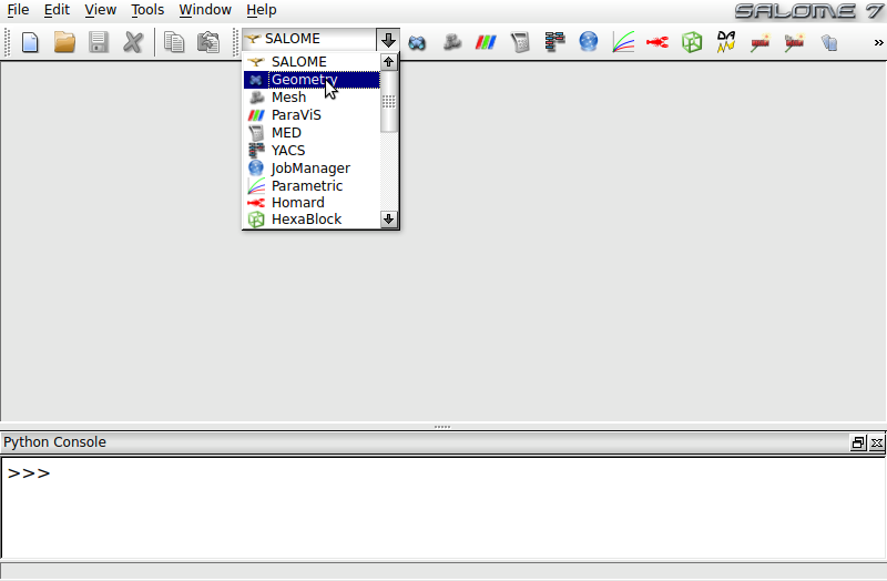
Fig. 7 Salome main program window. Select Geometry from dropdown menu in order to create your model.
Next we create a cylinder with a height of 1 that will serve a template for the stack layers. Click Create a cylinder in the toolbox as illustrated in Fig. 8. Select the right radio button in the register Cylinder and enter a Radius of 30 and a Height of 1 in the register Dimensions At Origin. Press Apply and Close to apply the scaling.
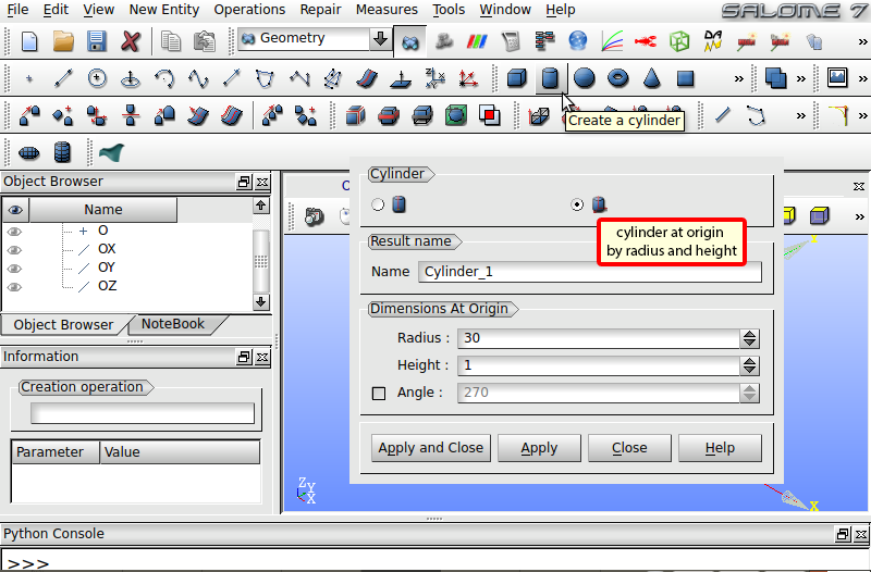
Fig. 8 Create generic cylinder with height 1 as template for the different layers of the stack.
In the next step the template cylinder is used to create the induvidual layers with different thicknesses. Select Operations -> Transformation -> Scale Transform in the menu bar as shown in the Fig. 9. Select the right radio button in the register Scale. Under Objects choose the template cylinder as basis object of the transformation. Use a Scale Factor of 1 in the x and y direction and 5 in the z-direction. Press Apply to create the new cylinder. Consecutively change the Scale Factor Z to 10, 1.5, 3 and 5 and press Apply to construct layers with the desired thicknesses. Afterwards close the window. The Object Browser on the left now contains the basis and 5 scaled layers.
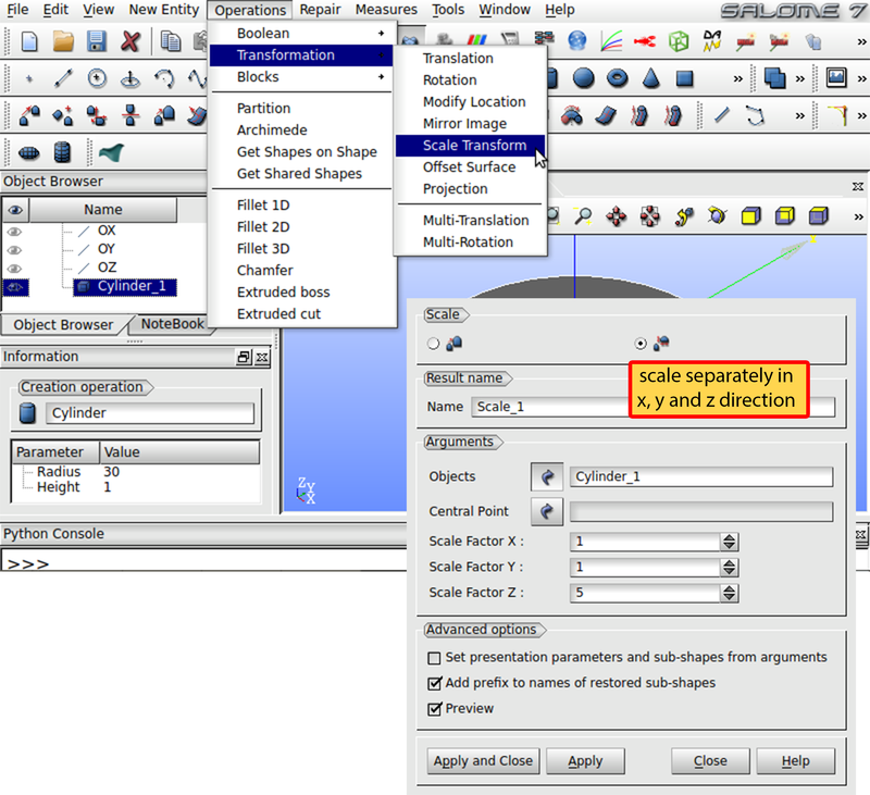
Fig. 9 Copy and scale the template cylinder in order to create the individual layers.
Next, we have to move the layers along the z-direction to construct the final model. Choose Operations -> Transformation -> Translation in the menu bar as shown in Fig. 10. Select the left radio button in the register Translation and choose layer Scale_2 with 10 height under Objects. Set Dx to 0, Dy to 0 and Dz to 5 for a shift of 5 in the z-direction. Uncheck Create a copy in order to merely transform the layer without duplicating it. Press Apply and shift layer Scale_3 by 15, Scale_4 by 16.5 and Scale_5 by 19.5 in the same way. Then close the window.
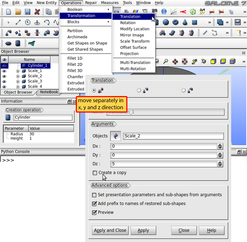
Fig. 10 Move cylinders vertically to create the complete multilayer stack.
So far the layers are not linked to each other. Hence, during the mesh process the borders between the layers would be treated separately and same surfaces would be discretized more than once. Click Partition in the toolbox as shown in Fig. 11, select the left radio button in the first register and choose the 5 scaled layers as Objects. Click Apply and Close to create the partition and then close the window. In order to generate IDs for different regions, we have to create groups.
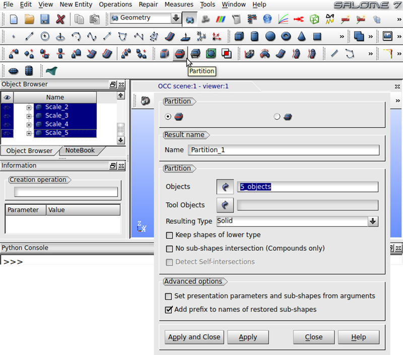
Fig. 11 Merge induvidual layers in order to generate a solid model of the multilayer stack that is aware of its layer structure when meshed.
Select the Partition_1 in the Object Browser and click New Entry -> Group -> Create Group in the menu bar as illustrated in Fig. 12. Under Shape Type choose the right radio button to use volumes for the grouping. The Main Shape has to be Partition_1. Next, click at the bottom layer in the viewer and press Add. Note, that you have to hide the original cylinder objects in the object browser in order to ensure that the member objects of the partition are selectable in the viewer window. Click Apply to create the group. Repeat for every layer of the model. The partition should then have 5 groups. The geometry is now ready to get meshed.
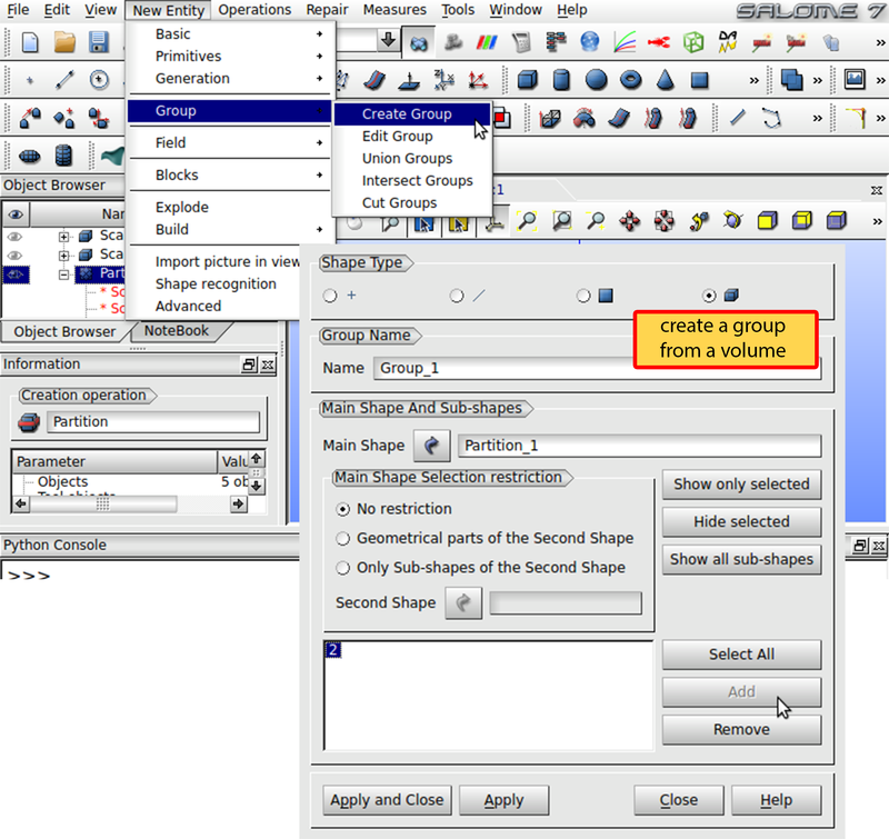
Fig. 12 Create a group for each layer to make the meshing module aware of the layers structure of the stack.
Change to the Mesh mode of Salome in the drop-down menu from the beginning. Click Mesh -> Create Mesh. Choose Partition_1 as Geometry. In the 3D register use Tetrahedron (Netgen) as Algorithm. Click Assign a set of hypotheses -> 3D: Automatic Tetrahedralization to determine a mesh length for the discretization. In the next window enter 5 under Length and close the window. Press Apply and Close to accept the mesh. In order to mark the mesh cells with IDs according to the generated groups, select Mesh_1 in the Object Browser and click Mesh -> Create Groups from Geometry in the menu bar as illustrated Fig. 13. Insert the 5 groups of Partition_1 under the register Elements and click Apply and Close as shown in the figure. Now the mesh can be created. Right click Mesh_1 in the Object Browser and select Compute. This should give you a of your geometry.
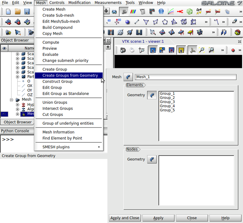
Fig. 13 Create mesh groups in order to mark the mesh cells of the individual layers with the layer ID.
The resulting mesh is best save a med file which can be converted by magnum.msh. Right click Mesh_1 in the Object Browser and select Export -> MED file to save the mesh. Don’t forget to save your Salome project. The MED file can be converted to a XML file with magnum.msh as described in Section Converting meshes.